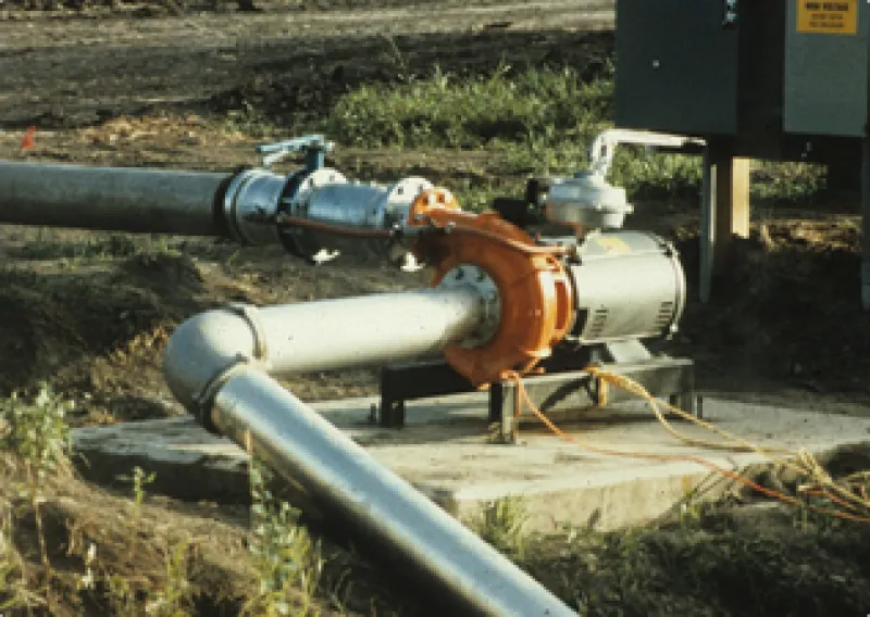
Deep-well turbine pumps are adapted for use in cased wells or where the water surface is below the practical limits of a centrifugal pump. Turbine pumps also are used with surface water systems.
Because the intake for the turbine pump is continuously under water, priming is not a concern. Turbine pump efficiencies are comparable to or greater than most centrifugal pumps. They usually are more expensive than centrifugal pumps and more difficult to inspect and repair.
The turbine pump has three main parts: head assembly, shaft and column assembly and pump bowl assembly, as shown in Figure 4. The head normally is cast iron and designed to be installed on a foundation. It supports the column, shaft and bowl assemblies and provides a discharge for the water. It also will support an electric motor, a right-angle gear drive or a belt drive.
Figure 4. A deep-well turbine pump.
The shaft and column assembly provides a connection between the head and pump bowls. The line shaft transfers the power from the motor to the impellers, and the column carries the water to the surface. The line shaft on a turbine pump may be water- or oil-lubricated.
The oil-lubricated pump has a hollow shaft into which oil drips, lubricating the bearings. The water-lubricated pump has an open shaft. The bearings are lubricated by the pumped water. If pumping fine sand is a possibility, select the oil-lubricated pump because it will keep the sand out of the bearings.
If the water is for domestic or livestock use, it must be free of oil, and a water-lubricated pump must be used. In some states, such as Minnesota, you have no choice; water-lubricated pumps are required in all new irrigation wells.
Line shaft bearings commonly are placed on 10-foot centers for water- lubricated pumps operating at speeds under 2,200 RPM and at 5-foot centers for pumps operating at higher speeds. Oil-lubricated bearings commonly are placed on 5-foot centers.
A pump bowl encloses the impeller. Due to its limited diameter, each impeller develops a relatively low head. In most deep-well turbine installations, several bowls are stacked in series one above the other. This is called staging. A four-stage bowl assembly contains four impellers all attached to a common shaft and will operate at four times the discharge head of a single-stage pump.
Impellers used in turbine pumps may be semi-open or enclosed, as shown in Figure 5. The vanes on semi-open impellers are open on the bottom and they rotate with a close tolerance to the bottom of the pump bowl.
Figure 5. Cutaway view of two enclosed impellers within their pump bowls.
The tolerance is critical and must be adjusted when the pump is new. During the initial break-in period, the line shaft couplings will tighten; therefore, after about 100 hours of operation, the impeller adjustments should be checked. After break-in, the tolerance must be checked and adjusted every three to five years or more often if pumping sand.
Both types of impellers may cause inefficient pump operation if they are not adjusted properly. Mechanical damage will result if the semi-open impellers are set too low and the vanes rub against the bottom of the bowls. The adjustment of enclosed impellers is not as critical; however, they still must be checked and adjusted.
Impeller adjustments are made by tightening or loosening a nut on the top of the head assembly. Impeller adjustments normally are made by lowering the impellers to the bottom of the bowls and adjusting them upward. The amount of upward adjustment is determined by how much the line shaft will stretch during pumping. The adjustment must be made based on the lowest possible pumping level in the well.
The pump manufacturer often provides the proper adjustment procedure. The adjustment procedure for many of the common deep-well turbine brands is outlined in Nebraska Cooperative Extension Service publication EC 81-760, titled “How to adjust vertical turbine pumps for maximum efficiency.”


